I did this Practice Exercise for CCNA Course ( Neil Anderson )
Stage 1
Initial Setup:
- All switches and routers were in factory default state.
- Verified VLAN database using
show vlan brief– only default VLANs existed.
Configuration Steps:
-
Checked default switchport settings using:
show interfaces switchport -
Configured trunk links between switches:
BASHinterface Gi0/1 switchport mode trunk switchport trunk native vlan 199 -
Configured VTP:
-
On SW1:
BASHvtp mode server vtp domain FLACKBOX -
On SW2:
BASHvtp mode transparent vtp domain FLACKBOX -
On SW3:
BASHvtp mode client vtp domain FLACKBOX
-
-
Created VLANs on SW1 (VTP Server):
BASHvlan 10 name ENG vlan 20 name SALES vlan 199 name NATIVE -
VLAN propagation:
- Verified VLANs automatically synced to SW3 (Client).
- SW2 remained unchanged (Transparent mode).
-
Set trunk native VLAN on all trunk ports for security:
BASHswitchport trunk native vlan 199 -
Configured access ports for PCs:
-
Example on SW3:
BASHint range f0/1 - 2 switchport mode access switchport access vlan 10 int f0/3 switchport mode access switchport access vlan 20
-
-
Resolved native VLAN mismatch errors:
- Matched native VLAN (199) on both sides of trunk links.
- STP blocking issues resolved.
Verification:
- Verified VLANs using:
show vlan brief - Verified trunk status:
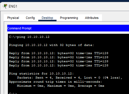
show interfaces trunk - Checked PC connectivity with
pingcommands (Eng1 - Eng3, Sales1 - Sales3)
Stage 2: Inter-VLAN Routing - Option 1
Using Separate Physical Interfaces on Router (R1)
Router (R1) Configuration
- Enable and assign IP addresses to interfaces:
-
FastEthernet0/0(for ENG VLAN):BASHinterface FastEthernet0/0 ip address 10.10.10.1 255.255.255.0 no shutdown -
FastEthernet0/1(for Sales VLAN):BASHinterface FastEthernet0/1 ip address 10.10.20.1 255.255.255.0 no shutdown
-
Both interfaces are UP and functioning
Switch (SW2) Configuration
-
VLAN Configuration:
-
VLAN 10 (ENG) and VLAN 20 (Sales) are already created:
BASHvlan 10 name ENG vlan 20 name Sales
-
-
Assign VLANs to Ports:
-
Fa0/1→ VLAN 10 (ENG):BASHinterface Fa0/1 switchport mode access switchport access vlan 10 -
Fa0/2→ VLAN 20 (Sales):BASHinterface Fa0/2 switchport mode access switchport access vlan 20
-
-
Trunk Port Configured:
-
Gig0/1set as trunk with native VLAN 199:BASHinterface Gig0/1 switchport trunk native vlan 199 switchport mode trunk
-
VLAN interfaces Vlan10 and Vlan20 are up
Verification Steps
-
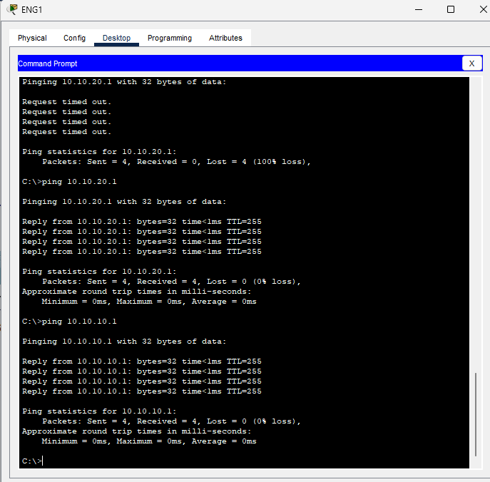
Connectivity from Eng1 (Fa0/1) to R1’s VLAN 20 (10.10.20.1)
(pending)
-
Connectivity from Eng1 to Sales1 (across VLANs)
Stage 3: Inter-VLAN Routing - Option 2
Router-on-a-Stick Configuration
Router (R1) Configuration
- Clear Existing IPs on Physical Interface
- Removed IPs from
FastEthernet0/0to prepare for subinterfaces.
- Removed IPs from
- Configure Sub-Interfaces on FastEthernet0/0:
-
For VLAN 10 (ENG):
BASHinterface FastEthernet0/0.10 encapsulation dot1Q 10 ip address 10.10.10.1 255.255.255.0 -
For VLAN 20 (Sales):
BASHinterface FastEthernet0/0.20 encapsulation dot1Q 20 ip address 10.10.20.1 255.255.255.0
-
Both sub-interfaces are UP and functional
*FastEthernet0/0 now acts as trunk carrying tagged VLAN traffic*
Switch (SW2) Configuration
-
VLAN Setup:
-
VLANs already exist:
BASHvlan 10 name ENG vlan 20 name Sales vlan 199 name NATIVE
-
-
Assign Access Ports:
-
Fa0/1to VLAN 10 (ENG)BASHinterface Fa0/1 switchport mode access switchport access vlan 10 -
Fa0/2to VLAN 20 (Sales)BASHinterface Fa0/2 switchport mode access switchport access vlan 20
-
-
Configure Trunk to Router:
-
Fa0/1(connected to R1’sFa0/0) as trunk:BASHinterface Fa0/1 switchport trunk encapsulation dot1q switchport mode trunk switchport trunk allowed vlan 10,20
-
Trunk operational and forwarding VLAN 10 and 20 traffic
-
Set Default Gateway on SW2:
BASHip default-gateway 10.10.10.1
Verification Steps
-
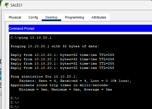
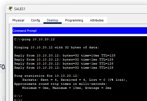
PC Eng1 (VLAN 10) should be able to:
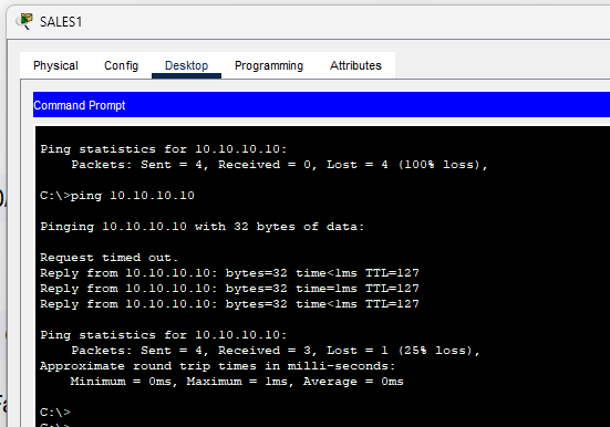
- Ping
10.10.20.1(R1’s subinterface for VLAN 20) - Ping Sales1 PC
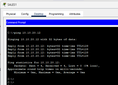
Pinging Sales 3 from Eng 1
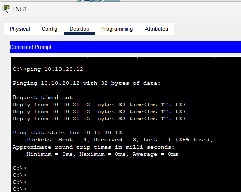
- Ping
Pinging Eng1 from Sales 1
Conclusion
This lab successfully demonstrated three critical aspects of VLAN implementation:
- Basic VLAN Configuration: Established proper VLAN segmentation with VTP configuration across multiple switches
- Traditional Inter-VLAN Routing: Implemented routing using separate physical interfaces, proving the basic concept of inter-VLAN communication
- Router-on-a-Stick: Successfully configured and tested a more scalable inter-VLAN routing solution using subinterfaces
Key Learning Outcomes:
- Understanding of different VTP modes and their impact on VLAN propagation
- Practical experience with both physical and logical inter-VLAN routing methods
- Troubleshooting skills for native VLAN mismatches and connectivity issues
All configurations were verified with successful ping tests between VLANs, demonstrating a fully functional network design.